stucture safty against earthquake

  • ۰
  • ۰

The conventional approach to earthquake resistant design of buildings depends upon providing the building with strength, stiffness and inelastic deformation capacity which are great enough to withstand a given level of earthquake-generated force. This is generally accomplished through the selection of an appropriate structural configuration and the careful detailing of structural members, such as beams and columns, and the connections between them.

But more advanced techniques for earthquake resistance is not to strengthen the building, but to reduce the earthquake-generated forces acting upon it.

Among the most important advanced techniques of earthquake resistant design and construction are:

  • Base Isolation
  • Energy Dissipation Devices

Base Isolation

A base isolated structure is supported by a series of bearing pads which are placed between the building and the building’s foundation. (See Figure 1.) A variety of different types of base isolation bearing pads have now been developed.

The bearing is very stiff and strong in the vertical direction, but flexible in the horizontal direction.
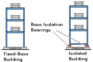
Base-Isolated and Fixed-Base Buildings

Figure 1: Base-Isolated and Fixed-Base Buildings

Earthquake Generated Forces

To get a basic idea of how base isolation works, examine Figure 2. This shows an earthquake acting on both a base isolated building and a conventional, fixed-base,building. As a result of an earthquake, the ground beneath each building begins to move. In Figure 2, it is shown moving to the left. Each building responds with movement which tends toward the right. The building undergoes displacementtowards the right. The building’s displacement in the direction opposite the ground motion is actually due to inertia. The inertial forces acting on a building are the most important of all those generated during an earthquake.

It is important to know that the inertial forces which the building undergoes are proportional to the building’s acceleration during ground motion. It is also important to realize that buildings don’t actually shift in only one direction. Because of the complex nature of earthquake ground motion, the building actually tends to vibrateback and forth in varying directions.
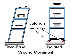
Base-Isolated, Fixed-Base Buildings

Figure 2: Base-Isolated, Fixed-Base Buildings

Deformation and Damages

In addition to displacing toward the right, the un-isolated building is also shown to be changing its shape-from a rectangle to a parallelogram. It is deforming. The primary cause of earthquake damage to buildings is the deformation which the building undergoes as a result of the inertial forces acting upon it.

Response of Base Isolated Building

By contrast, even though it too is displacing, the base-isolated building retains its original, rectangular shape. It is the lead-rubber bearings supporting the building that are deformed. The base-isolated building itself escapes the deformation and damage–which implies that the inertial forces acting on the base-isolated building have been reduced. Experiments and observations of base-isolated buildings in earthquakes have been shown to reduce building accelerations to as little as 1/4 of the acceleration of comparable fixed-base buildings, which each building undergoes as a percentage of gravity. As we noted above, inertial forces increase, and decrease, proportionally as acceleration increases or decreases.

Acceleration is decreased because the base isolation system lengthens a building’s period of vibration, the time it takes for the building to rock back and forth and then back again. And in general, structures with longer periods of vibration tend to reduce acceleration, while those with shorter periods tend to increase or amplify acceleration.

Image result for dampers in earthquake resistant buildings

Finally, since they are highly elastic, the rubber isolation bearings don’t suffer any damage. But the lead plug in the middle of our example bearing experiences the same deformation as the rubber. However, it generates heat. In other words, the lead plug reduces, or dissipates, the energy of motion–i.e., kinetic energy–by converting that energy into heat. And by reducing the energy entering the building, it helps to slow and eventually stop the building’s vibrations sooner than would otherwise be the case–in other words, it damps the building’s vibrations.

Energy Dissipation Devices

The second of the major new techniques for improving the earthquake resistance of buildings also relies upon damping and energy dissipation, but it greatly extends the damping and energy dissipation provided by lead-rubber bearings.

As we’ve said, a certain amount of vibration energy is transferred to the building by earthquake ground motion. Buildings themselves do possess an inherent ability to dissipate, or damp, this energy. However, the capacity of buildings to dissipate energy before they begin to suffer deformation and damage is quite limited. The building will dissipate energy either by undergoing large scale movement or sustaining increased internal strains in elements such as the building’s columns and beams. Both of these eventually result in varying degrees of damage.

So, by equipping a building with additional devices which have high damping capacity, we can greatly decrease the seismic energy entering the building, and thus decrease building damage.

Accordingly, a wide range of energy dissipation devices have been developed and are now being installed in real buildings. Energy dissipation devices are also often called damping devices. The large number of damping devices that have been developed can be grouped into three broad categories:

  • Friction Dampers: these utilize frictional forces to dissipate energy
  • Metallic Dampers : utilize the deformation of metal elements within the damper
  • Viscoelastic Dampers : utilize the controlled shearing of solids
  • Viscous Dampers: utilized the forced movement (orificing) of fluids within the damper

Fluid Viscous Dampers

General principles of damping devices are illustrated through Fluid Viscous damper. Following section, describes the basic characteristics of fluid viscous dampers, the process of developing and testing them, and the installation of fluid viscous dampers in an actual building to make it more earthquake resistant.

Damping Devices and Bracing Systems

Damping devices are usually installed as part of bracing systems. Figure 3 shows one type of damper-brace arrangement, with one end attached to a column and one end attached to a floor beam. Primarily, this arrangement provides the column with additional support. Most earthquake ground motion is in a horizontal direction; so, it is a building’s columns which normally undergo the most displacement relative to the motion of the ground. Figure 3 also shows the damping device installed as part of the bracing system and gives some idea of its action.
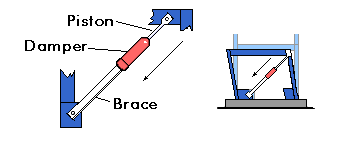
Damping Device Installed with Brace

Figure 3: Damping Device Installed with Brace

  • pouriya masrour
  • ۰
  • ۰

Seismic Retrofitting Techniques for Concrete Structures:

Seismic Retrofitting Techniques are required for concrete constructions which are vulnerable to damage and failures by seismic forces. In the past thirty years. Moderate to severe earthquakes occurs around the world every year. Such events lead to damage to the concrete structures as well as failures.

Thus the aim is to Focus on a few specific procedures which may improve the practice for the evaluation of seismic vulnerability of existing reinforced concrete buildings of more importance and for their seismic retrofitting by means of various innovative techniques such as base isolation and mass reduction. So Seismic Retrofitting is a collection of mitigation technique for Earthquake engineering. It is of utmost importance for historic monuments, areas prone to severe earthquakes and tall or expensive structures.

Keywords: Retrofitting, Base Isolation, Retrofitting Techniques, Jacketing, Earthquake Resistance

1. Introduction to Seismic Retrofitting Techniques:

  • Earthquake creates great devastation in terms of life, money and failures of structures.
  • Upgrading of certain building systems (existing structures) to make them more resistant to seismic activity (earthquake resistance) is really of more importance.
  • Structures can be (a) Earthquake damaged, (b) Earthquake vulnerable
  • Retrofitting proves to be a better economic consideration and immediate shelter to problems rather than replacement of building.

1.1 Seismic Retrofitting of Concrete Structures:


Definition:

It is the modification of existing structures to make them more resistant to seismic activity, ground motion, or soil failure due to earthquakes.

The retrofit techniques are also applicable for other natural hazards such as tropical cyclones, tornadoes, and severe winds from thunderstorms.

1.2 Need for Seismic Retrofitting:

  • To ensure the safety and security of a building, employees, structure functionality, machinery and inventory
  • Essential to reduce hazard and losses from non-structural elements.
  • predominantly concerned with structural improvement to reduce seismic hazard.
  • Important buildings must be strengthened whose services are assumed to be essential just after an earthquake like hospitals.

1.3 Problems faced by Structural Engineers are:


Lack of standards for retrofitting methods – Effectiveness of each methods varies a lot depending upon parameters like type of structures, material condition, amount of damage etc.,

1.4 Basic Concept of Retrofitting:

 The aim is at:

  • Upgradation of lateral strength of the structure
  • Increase in the ductility of the structure
  • Increase in strength and ductility

2. Classification of Retrofitting Techniques:

Seismic Retrofitting Techniques for Concrete Structures

Fig 1: Retrofitting Techniques for Reinforced Concrete Structures

2.1 Adding New Shear Walls:

  • Frequently used for retrofitting of non ductile reinforced concrete frame buildings.
  • The added elements can be either cast?in?place or precast concrete elements.
  • New elements preferably be placed at the exterior of the building.
  • Not preferred in the interior of the structure to avoid interior mouldings.

Additional Shear Wall

Fig 2: Additional Shear Wall

2.2 Adding Steel Bracings

  • An effective solution when large openings are required.
  • Potential advantages due to higher strength and stiffness, opening for natural light can be provided, amount of work is less since foundation cost may be minimized and adds much less weight to the existing structure.

Adding STEEL Bracings:


RC Building retrofitted by steel bracing

Fig 3: RC Building retrofitted by steel bracing

2.3 Jacketing (Local Retrofitting Technique):

This is the most popular method for strengthening of building columns.

Types of Jacketing:

  1. 1.Steel jacket,
  2. Reinforced Concrete jacket,
  3. Fibre Reinforced Polymer Composite (FRPC) jacket

Purpose for jacketing:

  • To increase concrete confinement
  • To increase shear strength
  • To increase flexural strength

Column Jacketing

Fig 4: Column Jacketing

Beam Jacketing

Fig 5: Beam Jacketing

2.4 Base Isolation (or Seismic Isolation):

Isolation of superstructure from the foundation is known as base isolation. It is the most powerful tool for passive structural vibration control technique.

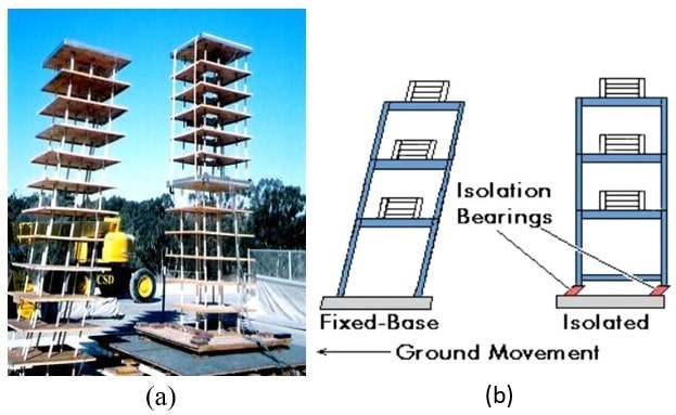
Base Isolated Structures (a)Model Under Test, (b) Diagrammatical Representation

Fig 6: Base Isolated Structures (a)Model Under Test, (b) Diagrammatical Representation

2.4.1 Advantages of Base Isolation

  • Isolates Building from ground motion – Lesser seismic loads, hence lesser damage to the structure, -Minimal repair of superstructure.
  • Building can remain serviceable throughout construction.
  • Does not involve major intrusion upon existing superstructure

2.4.2 Disadvantages of Base Isolation

  • Expensive
  • Cannot be applied partially to structures unlike other retrofitting
  • Challenging to implement in an efficient manner

2.5 Mass Reduction Technique of Retrofitting:

This may be achieved, for instance, by removal of one or more storey’s as shown in Figure. In this case it is evident that the removal of the mass will lead to a decrease in the period, which will lead to an increase in the required strength.

 Seismic Retrofitting by Mass reduction (removal of Storey)

Fig 7: Seismic Retrofitting by Mass reduction (removal of Storey)

2.6 Wall Thickening Technique of Retrofitting:

The existing walls of a building are added certain thickness by adding bricks, concrete and steel aligned at certain places as reinforcement, such that the weight of wall increases and it can bear more vertical and horizontal loads, and also its designed under special conditions that the transverse loads does not cause sudden failure of the wall.

3. Indian Standard Codes for Earthquake Design of Structures:

  • IS: 1893-2002 (part-1) Criteria for Earthquake Resistant Design of Structures (Part 1 : General Provision and Buildings) – Code of Practice
  • IS: 4326-1993 Earthquake Resistant Design and Construction of Buildings – Code of Practice
  • IS: 13920-1993 Ductile Detailing of Reinforced Concrete Structures subjected to Seismic Forces – Code of Practice
  • IS: 13935-1993 Repair and Seismic Strengthening of Buildings – Guidelines
  • IS: 13828-1993 Improving Earthquake Resistance of Low Strength Masonry Buildings – Guidelines
  • IS: 13827-1993 Improving Earthquake Resistance of Earthen Buildings – Guidelines

4. Conclusion – Seismic Retrofitting Techniques for concrete structures:

  • Seismic Retrofitting is a suitable technology for protection of a variety of structures.
  • It has matured in the recent years to a highly reliable technology.
  • But, the expertise needed is not available in the basic level.
  • The main challenge is to achieve a desired performance level at a minimum cost, which can be achieved through a detailed nonlinear analysis.
  • Optimization techniques are needed to know the most efficient retrofit for a particular structure.
  • Proper Design Codes are needed to be published as code of practice for professionals related to this field.

5. References:

  • Agarwal, P. and Shrikhande, M., 2006, Earthquake Resistant Design of Structures, 2nd Edition, Prentice-Hall of India Private Limited, New Delhi.
  • Cardone, D. and Dolce, M., 2003, Seismic Protection of Light Secondary Systems through Different Base Isolation Systems, Journal of EarthquakeEngineering, 7 (2), 223-250.
  • Constantinou, M.C., Symans, M.D., Tsopelas, P., and Taylor, D.P., 1993, Fluid Viscous Dampers in Applications of Seismic Energy Dissipation and Seismic Isolation, ATC-17-1, Applied Technology Council, San Francisco.
  • EERI, 1999, Lessons Learnt Over Time – Learning from Earthquakes Series: Volume II Innovative Recovery in India, Earthquake Engineering
  • Research Institute, Oakland (CA), USA.Murty, C.V.R., 2004, IITK-BMTPC Earthquake Tip, New Delhi.

Article By: SHAIK NASREEN, M.Tech Structural Engineering

  • pouriya masrour
  • ۰
  • ۰

tuned mass damper is a device mounted in structures to prevent discomfort, damage, or outright structural failure caused by vibration. They are used in high rise buildings to prevent failure of buildings during earthquakes. They are also known as an active mass damper (AMD) or harmonic absorber,

How Tuned Mass Dampers Work?

Tuned Mass Damper


Tuned Mass Damper Operating Frequency

A tuned mass damper (TMD) consists of a mass (m), a spring (k), and a damping device (c), which dissipates the energy created by the motion of the mass (usually in a form of heat). In this figure, M is the structure to which the damper would be attached.

From the laws of physics, we know that F = ma and a = F/m. This means that when an external force is applied to a system, such as wind pushing on a skyscraper, there has to be acceleration. Consequently, the people in the skyscraper would feel this acceleration. In order to make the occupants of the building feel more comfortable, tuned mass dampers are placed in structures where the horizontal deflections from the wind’s force are felt the greatest, effectively making the building stand relatively still.

When the building begins to oscillate or sway, it sets the TMD into motion by means of the spring and, when the building is forced right, the TMD simultaneously forces it to the left.

Ideally, the frequencies and amplitudes of the TMD and the structure should nearly match so that EVERY time the wind pushes the building, the TMD creates an equal and opposite push on the building, keeping its horizontal displacement at or near zero. If their frequencies were significantly different, the TMD would create pushes that were out of sync with the pushes from the wind, and the building’s motion would still be uncomfortable for the occupants. If their amplitudes were significantly different, the TMD would, for example, create pushes that were in sync with the pushes from the wind but not quite the same size and the building would still experience too much motion.

The effectiveness of a TMD is dependent on the mass ratio (of the TMD to the structure itself), the ratio of the frequency of the TMD to the frequency of the structure (which is ideally equal to one), and the damping ratio of the TMD (how well the damping device dissipates energy).

Wide span structures (bridges, spectator stands, large stairs, stadium roofs) as well as slender tall structures (chimneys, high rises) tend to be easily excited to high vibration amplitudes in one of their basic mode shapes, for example by wind or marching and jumping people. Low natural frequencies are typical for this type of structures, due to their dimensions, as is their low damping. With GERB Tuned Mass Dampers (TMD), these vibrations can be reduced very effectively.

The Tuned Mass Damper may consist of:

  • Spring
  • Oscillating Mass
  • Viscodamper

Tuned Mass Damper System

Fig. Tuned Mass Damper

as main components, or may be designed as a pendulum, also in combination with a Viscodamper.
Each TMD is tuned exactly to the structure and a certain natural frequency of it. Such TMD have been designed and built with an oscillating mass of 40 to 10.000 kg (90 to 22.000 lbs) and natural frequencies from 0.3 to 30 Hz. Vertical TMD are typically a combination of coil springs and Viscodampers, while in case of horizontal and torsional excitation in the corresponding horizontal TMD the coil springs are replaced by leaf springs or pendulum suspensions.

Building Vibrations During Earthquake

Fig. Amplitude – Frequency response of a low damped system without (blue) and with (yellow) tuned mass damper

Applications of Tuned Mass Dampers:

Tuned mass dampers are mainly used in the following applications:

  • Tall and slender free-standing structures (bridges, pylons of bridges, chimneys, TV towers) which tend to be excited dangerously in one of their mode shapes by wind,
  • Stairs, spectator stands, pedestrian bridges excited by marching or jumping people. These vibrations are usually not dangerous for the structure itself, but may become very unpleasant for the people,
  • Steel structures like factory floors excited in one of their natural frequencies by machines , such as screens, centrifuges, fans etc.,
  • Ships exited in one of their natural frequencies by the main engines or even by ship motion.

Tuned Mass Dampers may be already part of the structure’s original design or may be designed and installed later.

Example of Tuned Mass Damper Application:

Taipei structure has TMD of weight 730 tonnes which is show in below figure:

Tuned Mass Damper in Taipei Structure

  • pouriya masrour